 S-Video Board
Dell™ Inspiron™ 1525/1526 Service Manual
The system board's BIOS chip contains the Service Tag, which is also visible on a barcode label on the bottom of the computer. The replacement kit for the system board includes media that provides a utility for transferring the Service Tag to the replacement system board.

|
CAUTION: Before you begin the following procedure, follow the safety instructions in the Product Information Guide. |

|
1 |
processor heat sink fan cable connector |
2 |
button board cable connector |
|
3 |
speaker cable connector |
4 |
wireless sniffer board connector |
|
5 |
system board |
|
|

|
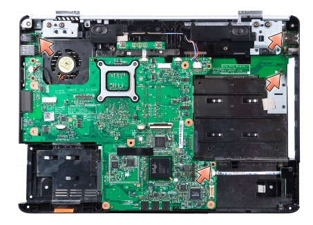
NOTE: Depending on your system configuration, the number of screws shown may be greater than the number of screws present in your system. |
|
|
CAUTION: Before you begin the following procedure, follow the safety instructions in the Product Information Guide. |

|
NOTICE: Ensure that any loose cables do not get caught beneath the system board. |
|
|
CAUTION: Before you begin the following procedure, follow the safety instructions in the Product Information Guide. |
|
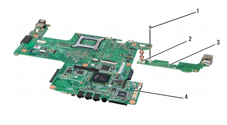
1 |
screw |
2 |
S-Video connector |
|
3 |
S-Video board |
4 |
system board |
|
|
CAUTION: Before you begin the following procedure, follow the safety instructions in the Product Information Guide. |
|
|
CAUTION: Before you begin the following procedure, follow the safety instructions in the Product Information Guide. |
|
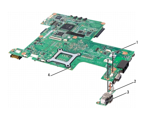
1 |
screws (2) |
2 |
charger board connector |
|
3 |
charger board |
4 |
system board |
|
|
CAUTION: Before you begin the following procedure, follow the safety instructions in the Product Information Guide. |