 Display Assembly
Dell™ Inspiron™ 1525/1526 Service Manual
Camera and Microphone Assembly

|
CAUTION: Before you begin the following procedure, follow the safety instructions in the Product Information Guide. |
|
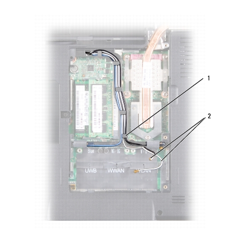
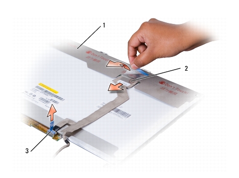
1 |
securing tabs |
2 |
antenna cables |

|
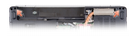
1 |
display cable |
2 |
camera cable |

|
1 |
display assembly |
2 |
antenna cables |
|
3 |
camera cable |
4 |
display cable |
|
5 |
Hinge screws (4) |
|
|
|
|
CAUTION: Before you begin the following procedure, follow the safety instructions in the Product Information Guide. |

|
NOTE: Ensure that the display cable, camera cable, and antenna cables are properly routed and secured beneath the plastic tabs. |
|
|
CAUTION: Before you begin the following procedure, follow the safety instructions in the Product Information Guide. |
|
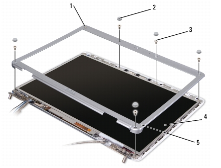
1 |
captive screw |
2 |
rubber display bumpers (6) |
|
3 |
shoulder screws (5) |
4 |
display panel |
|
5 |
display bezel |
|
|

|
NOTICE: Removal of the bezel from the display back cover requires extreme care to avoid damage to the bezel and the display panel. |
|
|
CAUTION: Before you begin the following procedure, follow the safety instructions in the Product Information Guide. |
|
|
CAUTION: Before you begin the following procedure, follow the safety instructions in the Product Information Guide. |
|
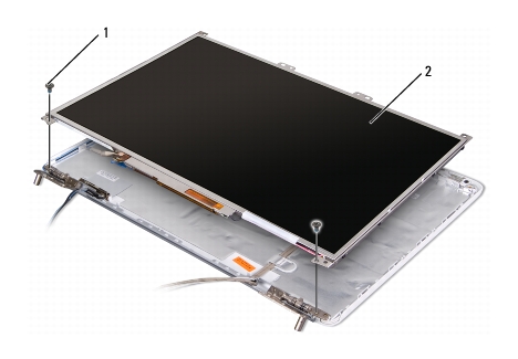
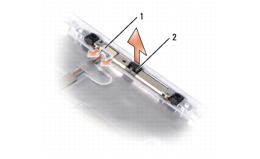
1 |
screws (2) |
2 |
display panel |

|
1 |
display panel |
2 |
screws (8) |
|
1 |
display panel |
2 |
top flex-cable connector |
|
3 |
bottom flex-cable connector |
|
|
|
|
CAUTION: Before you begin the following procedure, follow the safety instructions in the Product Information Guide. |
|
|
CAUTION: Before you begin the following procedure, follow the safety instructions in the Product Information Guide. |
|
1 |
camera cable connector |
2 |
camera/microphone assembly |
|
|
CAUTION: Before you begin the following procedure, follow the safety instructions in the Product Information Guide. |